The old mechanical regulator and the new Chrysler regulator, part #VR733 from Autozone. I also bought a connector for it, but you can just use bullet terminals.
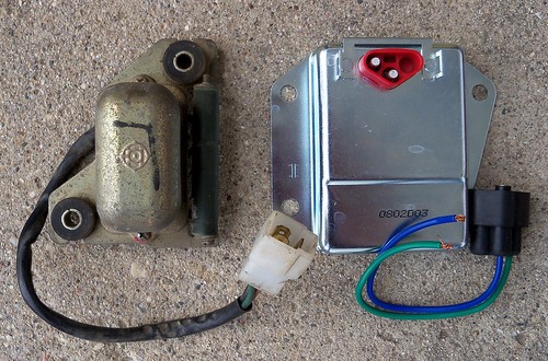
The old rectifier, and two 276-1185 full-wave bridge rectifiers from Radio Shack.
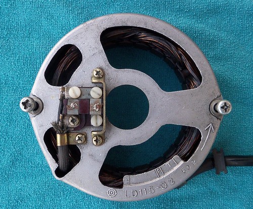
The Chrysler regulator needs the alternator to be modified to work like '80-'84 models by isolating the inner brush. This is done by replacing three steel screws with nylon. The nylon screw were the only thing I didn't buy locally. I bought a 10 pack for under $4 shipped from ebay seller AMS Bugbolts in the UK.
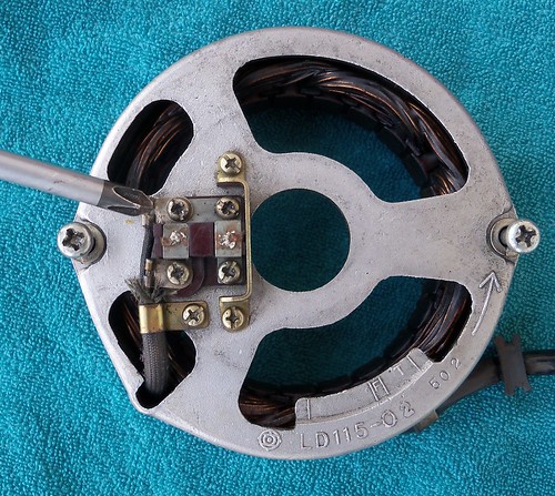
The M4 12mm nylon screws in place.
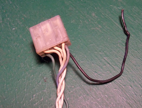
This is the alternator connection on the main harness. The black wire was ground, but needs to go to a switched 12V power source (brown wires) with an inline fuse.
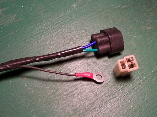
The new regulator connector soldered in place. Green to green, and blue to brown. The Chrysler regulator grounds through the case, so the black wire gets a ring terminal.
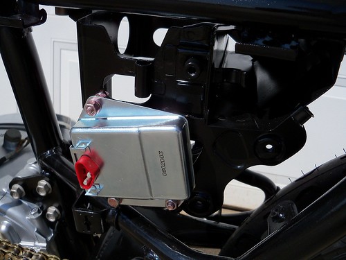
There are many ways to mount the regulator. I used one existing mount (bottom front), and drilled two holes in the battery box for the rest.
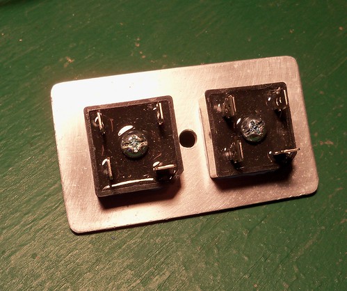
I had some scrap 1/8" x 2" aluminum flat stock and cut a 3.5" piece to make the heat sink/mount for the rectifiers. Heat sink compound is used for this.
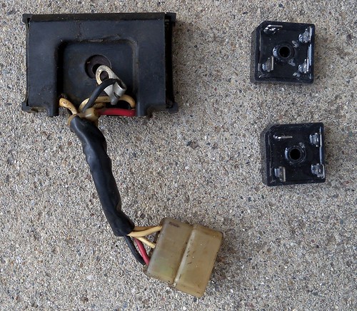
The original connector cleaned up nicely and was in good shape, so I reused it.
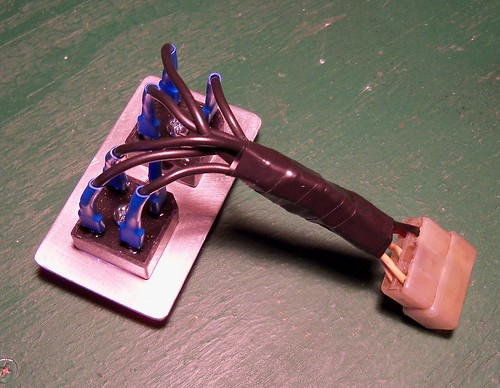
Done and mounted. The rectifier mounts in the stock location under the battery box.
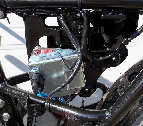
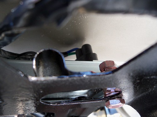
This is with the side cover on to check clearance. The wires are close, so I'll probably use some stick-on foam to make sure they don't ever rub.
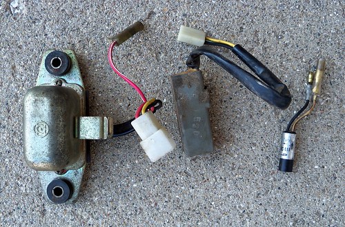
A few more electrical parts, the bigger one on the left is the 'safety relay', which I'm going to keep. It cuts power to the starter once the engine is running. I don't know why they thought it was needed, but I guess it doesn't hurt anything. The gray box in the middle is the 'light checker' and the small cylinder on the right is a diode for the brake lining switch. Both of those won't be used. I went through the harness and removed the wires for them also.
No comments:
Post a Comment